Hi guys, I am eager to write about this topic because I am believing that this post will clear your doubts about the electrical equipment capacitor voltage transformer also known as CVT.
CVT's full form in electrical engineering is Capacitive Voltage Transformers, which are used at high voltage transmission substations.
How does CVT works?
A capacitive voltage transformer *CVT is a device that step down the high voltage (HV) signal to low-voltage (LV) signal for measurement purposes.
The other names for CVT are Capacitive voltage transformer, Capacitor potential transformer, coupling capacitor voltage transformer.
Voltage rated above 33KV is called high voltage(HV) as well as voltage rated below 1000 V is called low voltage(LV)
Practically CVT also called CCVT (Coupling capacitor voltage transformer). Mainly used in a substation rated above 132 kV.
The other name for capacitor voltage transformer is a Capacitive potential transformer.
Do you Know?
The characteristics of a Capacitive voltage transformer are much like a regular Potential transformer.
Small clarification on Potential transformer
- The Potential transformer is a device used in switchgear and switchyard to produce an alternating voltage on its secondary winding, which is proportional to the alternating voltage on its secondary side.
- The output voltage of secondary winding is used for the metering, protection, and controlling process.
The Potential transformer is also called a Voltage transformer.
Why is a capacitor used in a capacitive voltage transformer (CVT)?
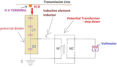
- The capacitor act as a potential divider or voltage divider in a CVT. This allows the CVT to step down the high voltage signal without the need for a magnetic core. This makes CVT reduced size and cost with increased efficiency.
- The impedance of capacitor typically inversely proportional to the frequency of signals.
For instance, a voltage transformer or potential transformer consumes a high amount of insulation for step down high voltage such as above 132 kV. This high amount of insulation increases the cost, weight, and size of the potential transformer. Economically this is not feasible.
But capacitive voltage transformer requires only a small amount of insulation for step down high voltage such as above 132kV. This low amount of insulation reduces the cost, weight, and size of the potential transformer.
3 segment of Capacitive Voltage Transformer
Capacitive voltage transformer mainly comprised or constructed of 3 segments.
- Potential Divider.
- Resonant Circuit.
- Metering unit.
Potential divider: Generates a fractional output voltage (Vout) of the input voltage (Vin).
Resonant circuit: If reactances in a circuit cancel each other then the circuit is called a resonant circuit.
Metering unit: The circuit which connects instrumentation devices is called a metering circuit.
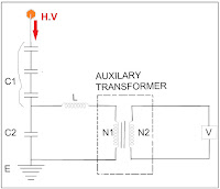
Circuit diagram of Capacitive Voltage Transformer
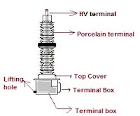
Construction of Capacitive Voltage Transformer
- High voltage terminals
- High voltage and Intermediate voltage capacitor
- Electro-magnetic unit
- Intermediate transformer
High voltage terminal
The high voltage terminal of the capacitive voltage transformer is made of highly conductive material. This terminal is connected directly to the transmission line in the substation. Terminals of the CVT have the capability to receive phase voltage(√3 times lesser than line voltage).
Capacitors in CVT
- High voltage capacitor (C1)
- Intermediate capacitor (C2)
The high and intermediated voltage capacitors are comprised inside the CVT in series. The capacitors are the first thing to meet the high voltage. Both capacitors act as potential dividers.
The insulation of the capacitive voltage transformer is made up of a polypropylene paper insulation system that is impregnated with insulator capacitor oil.
High voltage capacitor(C1)
Several high voltage condensers up to 1000 pf coupled together in the series act as a high voltage capacitor. So capacitor voltage transformer is also called a coupling capacitor. Capacitor bank connected in series can withstand high voltage above 300 kV.
Intermediate capacitor(C2)
The intermediate capacitor act as a standard low voltage condenser that is connected in series at several distances.
Electromagnetic unit
Intermediate transformer
The intermediate transformer is a step-down voltage transformer connected across the capacitor circuit to step down the high voltage signal into a low voltage signal.
Application of CVT
- Voltage measurement
- with Protection units such as a relay.
- For controlling devices such as energizing circuits.
Advantage of Capacitor voltage transformer
The capacitor voltage transformer is providing more accuracy in metering, protection, and controlling.


hv film capacitor manufacturer This particular is usually apparently essential and moreover outstanding truth along with for sure fair-minded and moreover admittedly useful My business is looking to find in advance designed for this specific useful stuffs…
ReplyDeleteDC link capacitors Thank you because you have been willing to share information with us. we will always appreciate all you have done here because I know you are very concerned with our.
ReplyDeleteUseful
ReplyDelete