We know, there is a high demand for electrical energy. This high demand for electrical energy leads to the fast development of electrical equipment. Electricity generation is decided based on the power consumption rate.
High power consumption leads to high electricity generation.
High electricity generation requires high protection against electric faults.
Protection equipment such as circuit breakers, lightning arrestors, and fuses, clears the electrical fault before it damages the power system.
During the process of fault clearance or maintenance, it is important to isolate the circuit from live equipment such as power sources. To do this, isolator or disconnecting switches are preferred to install in substations and power plants.
Here you can learn about isolators or disconnect switches,
Isolator in substation
Among the development of electrical equipment, a disconnecting switch is one of the valuable electrical devices for providing safety to employees and substations. An isolator or disconnector switch is an off-load switch used to isolate the H.V. equipment from the live circuit in off-load condition.
The operation of the disconnect switch or isolator is similar to the 'electrical switch which can be operated manually or automatically under No load condition
Manufacturers and designers follow IEC: 62271-102 (International electrotechnical commission) to design isolators.
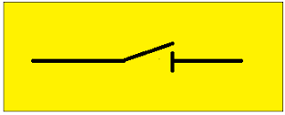
The isolator is also called a disconnecting switch. Because it operates and functions as an electrical switch. The electrical symbol for the isolator or disconnect switch is shown in the figure below.
Isolator or disconnect switch symbol
To represent the isolator or disconnector in a single-line diagram, designers use a standardized symbol. The standard symbol for the isolator is shown below.
 |
| The electrical symbol for the disconnector |
Overview of Disconnect switch or isolator
- Disconnectors or Isolators are used to isolate the high-voltage equipment such as (Busbars, Circuit breakers, and Power transformers), from the circuit under no-load conditions.
- The isolator is designed to operate at Off-Load conditions because it does not have any arc quenching medium to suppress the arc during On-load conditions.
- Some disconnecting switches come with an earth switch to discharge voltage or current into the earth before making the disconnector switch to off condition (no-load condition). This type of disconnecting switch is designed to work with interlock conditions.
Conditions for operating isolators or disconnect switch
We have to keep the disconnect switch at 'On position' (close) during the time of operation of the substation. We have to change the 'Off position' (open) when at the time of maintenance.
Interlock conditions for switching isolator
During open conditions-
- The circuit breaker opens first.
- The isolator opens only after opening the circuit breaker.
- Earthing switches are closed after opening the isolator.
During close conditions-
- The Earthing switches close first.
- The isolator closes only after the closing of the isolator.
- Circuit breakers are closed after closing the isolator.
By installing an isolator switch, in a substation or Industry, we can ensure personnel safety, at the time of maintenance.
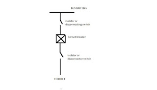
The above single line diagram clearly explains that disconnect or isolator switches(T1 and T2) have connected on both sides of a circuit breaker. During functional check or repair the circuit breaker, disconnecting switches, or isolator switch(T1) has to be in the open position from the busbar and T2 is also in the open position to disconnect the circuit breaker completely from the circuit or feeder.
In simple words, during the maintenance time, two disconnecting switches should be in Open condition, and the Circuit breaker also be in the open position.
Key points to remember
- Disconnecting switches are offload switches ie, they can operate only with no power supply.
- Used to isolate the high voltage equipment from live components during service.
Types of the disconnect switch or Isolator
Disconnecting switches can be classified into various types based on their operation, construction, and mounting arrangement. The major and basic types are.
Center break disconnector switch
Consider the below circuit for the R phase. The line enters one end of the disconnect switch and leaves the other side. Center break disconnector switches have two insulation poles for one phase(R).
At the Centre break disconnector switch, the blade or conductive rod of a disconnector switch breaks at the center point and opens the circuit. Two ends of the disconnect switches are stationary but the center is movable. The conductive rod opens upwards on its center, and because of its center breaking operation, it gets the name 'center break disconnect switch'.
Double End breaks the disconnector switch.
Consider the image for the R phase. The line enters one end of the disconnect switch and leaves the other side. The Centre break disconnector switches have three insulation poles for one phase(R).
A blade or conductive rod of a Centre insulation pole is a rotatory part, the rotor insulation pole rotates the blade clockwise and opens the circuit. While it's rotating, the two ends of the conductive rod avoid touching the other two sides of the pole.
Horizontal knee break disconnector switch
The disconnector switch has a horizontal conductive rod or blade which has an elbow or knee structure at the center point. While at the time of operation, the knee point of the conductive rod folds like human legs as shown in the image.
Pantograph break disconnector switch.
Pantograph meaning.
The pantograph is a linkage mechanism, which helps to produce one particular path for operation.
The pantograph breaks disconnector switches normally in a vertical position. It can be classified into two.
- Horizontal pantograph disconnector switch.
- vertical pantograph disconnector switch.
- Double arm vertical pantograph disconnector switch.
Horizontal Pantograph disconnector switch
A horizontal pantograph disconnector consists of a horizontal blade to disconnect the circuit or feeder in a horizontal position. The horizontal conductive rod is a pantograph mechanism.
Vertical pantograph disconnector switch
A vertical pantograph break disconnector switch consists of a vertical blade. pantograph linkage mechanism is provided in a vertical position. So it is called a Vertical Pantagraph break disconnector switch. This linkage mechanism is movable from upward to downward while disconnecting.
Double arm pantograph disconnector switch
Operation of double arm Pantograph. (500 kV Pantograph disconnector)
The double-arm pantograph disconnector switch consists of two vertical blades, These two blades are working parallelly and disconnect the circuit as same as a vertical pantograph. In modern days most industries and substations prefer this disconnector switch.
Advantages and disadvantages of Disconnect switches.
Advantage.
- It provides high safety for the technician and substation electrical equipment.
- Highly secure and blades are designed to withstand overcurrent than its rated current.
- It can make the substation completely de-energized and its operation is visible to the eyes.
- Construction is rugged and easy to install.
Disadvantage.
- It can operate only in no-load conditions.
- If no proper discharge is done there will be sudden arcing occur.
- Sudden arcing cannot be quenched immediately because it is installed in an open atmosphere.
- If the disconnect switches opened under load conditions then the arcing cannot control it and destroy the blades of the disconnector switch.


