Hi friends, welcome to my website please read further to gather a lot of information about power transfer.
This article gives you a detailed view of the A.C electrical power Transmission system, A.C Distribution system, Voltage control method, effects on the transmission line, the parameter of the transmission line, etc.
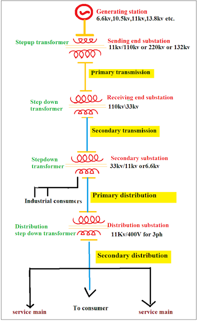
After the power is generated, the transmission and distribution process will start. The flow of electrical energy from generating station to consumers consists of two main components that are Transmission system and Distribution system.
This transmission system covers two main portion
- The primary transmission system, and
- Secondary transmission system
The distribution system covers two main portion
- Primary distribution system, and
- Secondary distribution system.
The operating voltage of Transmission and distribution depends on the quantum of power to be received or transmitted and the length of the transmission line. Operating voltage in India can be from 11 KV to 765 Kv. The highest transmission voltage in India is 765 KV.
Because of the variation of load at the consumer side, the current and voltage tolerance of the transmission line should be in + or - 5% to 10%.
The line which transfers power from one place to another is called a transmission line.
Structure of Power system.
If a long conductors transmit power over a long distance of several miles, it is called a transmission line. Suppose, the transmission line carries power up to 50 km then this transmission line considers as Short-line.
A short-line is denoted as 'lumped series impedance'. Above 50 km it is called medium or long line and this is denoted by "π". The transmission line transmits "High voltage" or "Extra-high voltage".
Because of transmission of high and extra-high voltage, a large number of transmission losses will occur. Transmission line losses are i) Copper loss ii) Die-electric loss iii) Induction loss.

Transmission system.
At the Power station, the bulk amount of electricity is generated. The generated voltages are rated at 6.6 kV, 10.5 kV, 11 KV, 13.8 kV, 15.75 kV, 33 kV, and above. But unfortunately generating stations are located far away from the consumer. But we need to transmit a sufficient amount of electrical energy to the consumers without any interruption.
The transmission system transfers power from generating station to the secondary substation at specified voltages, frequency, and waveform.
From the generating station or power station to the consumers, electricity flows through various substations such as Sending end substation, Receiving end substation, Secondary substation, and Distribution substation.
Transmission systems are often divided into Primary transmission and Secondary transmission. Both the transmission systems are connected through two substations one is Sending end substation and another one is Receiving end substation.
Primary transmission system.
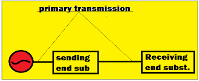
The primary transmission system transmits a huge amount of electrical energy from generating station to receiving end substation with the assistance of electric lines. The high voltage transmission line interconnects the generating station, sending end substation and receiving end substation.
The substation which is situated near the power plant is called "Sending end substation." The sending end substation receives generated voltage from generating station, directly without stepping up. At the sending end substation, a step-up transformer is installed to increase the generated AC voltage to an enormous quantity and send it to the receiving end substation.
At the primary transmission, line voltages are often transmitted at 110 KV, 132 KV, 220 KV, 400 KV, or 765 KV. This is 3 phase, 3 wire system.
Secondary transmission system.
The transmission line which transmits the step-down voltage (33 KV etc.,) from the receiving end substation to the secondary substation is called a Secondary transmission line. This is also a 3 phase 3 wire system.
The Receiving end substation was installed with a step-down transformer. The step-down transformer decreases the high voltage and sends the voltage to the secondary substation through the transmission line. The step-down transformer rating may differ according to power generation and distribution.
Distribution system.
The distribution system receives bulk power from the transmission systems at the receiving station. Voltage rating usually at (132 kV or 220 kV).
The consumer receives power through the Distribution system. The distribution system is located nearest to the consumer. It reduces the required voltage to the consumers with the help of secondary substations and distribution substations. The distribution system step-down the voltage to the various consumers such as Industrial consumers, domestic consumers, commercial consumers,. The bulk power source such as secondary substation and distribution substation connected to the consumer's load.
- Primary distribution system.
- Secondary distribution system.
Primary distribution line.
The primary distribution line mostly connects from the secondary substation to distributed substation.
Did you know?😮
Not only distribution substation connected with secondary substation, but big consumers need of medium voltage (11kv) also connected with the secondary substation.
Secondary distribution line.
In the electrical distribution system, the secondary distribution system is the last stage of delivering power to individual consumers such as domestic areas, household areas, Commercial areas. The secondary distribution line carries 'low voltage' to the consumer. The low voltage range from '110 v to 1 kV.
At the distribution substation, they install a distribution transformer to step down the medium voltage to low voltage. They maintain the frequency by 50 Hz or 60 Hz, which depends on the region.
The basic requirement of a power transmission system.
The power transmission system should transfer power from generating station to load end at specified voltages, frequency, and waveform without interruption of Radio-frequency or TV frequency, etc,.The transmission loss should be in less quantity. The Cost of the transmission line is very low.
Voltage control of transmission line.
- Tap changing transformers helps to change the voltage. The tap changing transformer available in both On-load and Off-load conditions.
- By using Shunt capacitors at the receiving end during heavy load or low power factor loads. Operation is achieved by switching on and off at a shunt capacitor.
- Switching in shunt reactors during low load conditions by neutralizing the effect of shunt capacitance of the long transmission line. We use this method only for a long transmission line.
- Voltage can also be control by static var compensator (SVC) in a substation.
- The Intermediate substation is at every interval of 300 km for a long A.C transmission line for installing shunt capacitor, shunt reactors and shunt capacitors, and SVS.
Application of shunt capacitor.
Application of the shunt reactor.
They switch on shunt reactors during low loads to compensate for the effect of shunt capacitance of the transmission line and control the voltage. We switch them off during heavy load. They only use this for a long transmission line.
Parameters of a transmission line.
The transmission line has three basic parameters because of the conductor material used in the transmission line and the flow of alternating current in the transmission line.
- Resistance Ω/ф ohms per phase.
- Inductive reactance in series XL=2πfl ohms per phase.
- Shunt capacitive reactance XC=1/2πfc ohms per phase.
Surge impedance of transmission line.
Surge impedance of transmission line the following gives Zs
Surge impedance loading.
Whenever the line is loaded, then the load impedance (Z=R+j X) is equal to the surge impedance of the line, The power carried by the line is called surge impedance loading, i.e.,
Pn = VI
VI = V^2/Zs
Two major effects on the transmission line.
Major effects on the conductor or transmission line, Due to the flow of alternating current in the transmission line,
Skin Effects.
The skin effect occurs because of high-frequency (3khz to 250 kHz) alternating current and brief pulse of current. The current density is larger near the surface of the conductor.
In alternating currents, the current density near the surface of the conductor is higher than that at the axis because of magnetic flux linkage.
This self-inductance of change in current causes a higher current flow near the surface of the conductor. The skin Effect causes an increase in the d.c resistance of the conductor.


wow very informative article i love it! can you recommend me power cables wholesale? thanks
ReplyDeleteyey I found the one! If you're looking for power cables wholesale. I recommend amwire you can visit their website.
ReplyDelete